73 Specifications
Tech articles
My Mustang
Stick it to it with a Tremec
|
Background
I began searching for an overdrive alternative to the C4 transmission in my 73 mustang when my C4 transmission stopped shifting to third gear regularly. I decided that I wanted to go with a manual transmission due to the relative ease of repair and rebuild of manual transmissions compared to automatics. My first choice was the T5 transmission installed in a number of Ford vehicles from 1986 to 1996. Torque ratings for the T5 ranged from 265 to 310 ft/lbs over the years and these transmissions were placed behind both 4 and 8 cylinder engines. The most desirable of the T5s are those from the 90 to 93 Mustang GTs and Mustang Cobras. After extensive research and some simple math calculations I decided against installing a T5 transmission into my 73 mustang because of the high amount of torque produced by my engine. I decided to go with a Tremec 3550 transmission. The Tremec 3550 weighs 100 lbs. Although the Tremec 3550 uses a different bellhousing and is larger transmission it is a direct replacement for the T5 transmission. The Tremec 3550 has a 350 ft/lbs torque rating. There is also a heavy duty version of the Tremec 3550 called a Tremec TKO with a torque rating of 400 ft/lbs.
Finding a Tremec I spent a month searching the internet looking for a tremec transmission. I found one on ebay and got it for 800 dollars. There are a number of companies that sell these transmissions new or rebuilt. I would recommend that you buy a new or rebuilt tremec to insure that you get one in proper working order. I also purchased a used bellhousing and flywheel.
Transmission Sales and Service http://www.ttcautomotive.com/English/products/tremec.asp http://www.hanlonmotorsports.com/ http://www.standardtransmission.com/tremec.html http://www.darkhorseperformance.com http://www.autoworks.cc/65-70_clutch_kit_instructions.htm
Parts I needed:
Down and Dirty The actual transmission swap took me a month and a half to complete. Most of that time was just down time for my car while I got parts and money collected. I would say that I spent 30 hours working on installing the tremec. Then I spent another 40 hours messing with constructing a clutch actuation system (it was a major pain). The only other part that gave me some worries was locating a crossmember for my application. There are a number of companies who sell crossmembers and whole T5/Tremec swap kits for early mustangs, unfortunately none of them sells a kit for 71-73 mustangs. I moved forward with the transmission swap and figured I would fabricate one (rig one up) after I had the Tremec in place. Luckily, before I got that far in the swap, I stumbled across a website where a guy doing a T5 swap in a mustang II modified his old crossmember and used it to mount the T5. After doing some measurements I discovered that I could also modify my old crossmember to mount the Tremec in my mustang.
For more info check out these links: http://www.mustangworks.com/articles/drivetrain/GetaGrip.html http://www.fordmuscle.com/archives/2000/09/t5swap/index.shtml http://www.stangnet.com/tech/t5swap.html
My Installation Steps
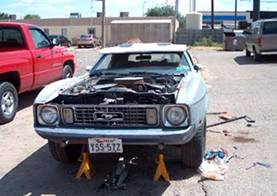
Transmission Removal 1. Disconnected the negative battery cable and then raised my mustang up and placed it on jack stands.
My baby up in the air 2. Disconnected the driveshaft and removed it 3. Removed the starter and transmission cross member 4. Disconnected hydraulic and vacuum lines from the C4 5. Removed the torque converter nuts 6. Placed a jack under the C4 and then removed the bolts in the bellhousing 7. Removed the C4 8. Removed U joints from the driveshaft Trip to the Machine and driveshaft shop to…
Note: I intended to also have my used flywheel resurfaced but the machinist said that my flywheel didn’t need it.
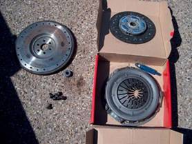
Flywheel, Clutch and Bellhousing installation Note: Before installing the clutch and pressure plate to the flywheel be sure to check that the clutch disk gear matches the spline count on the input shaft and that the disk fits onto the transmission input shaft.
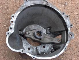
Bellhousing With Clutch fork inside Flywheel, Clutch, Pressure Plate Pilot Bearing and Flywheel Bolts
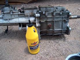
Tremec install Note: It is easier to work the transmission around in the transmission tunnel if you remove the shifter. Just be sure to reinstall the shifter threw the shifter hole in the transmission tunnel before you move the transmission to far forward.
Note: I could have filled the Transmission through the shifter later and missed out on getting to see what Syncro Mesh taste like.
Tremec and Syncromesh
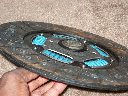
Note: Steps 10-27 are not necessary if you check to make sure the clutch disk gear matches the tremec’s input shaft
Ruined Clutch Disk: The gear in the center is pushed out and cracked
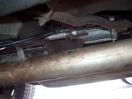
Modified Crossmember: The bolt is an 8” grade 8 3/8 bolt with a locking nut. To use my old crossmember I simply had to cut off the lip from one side and move it to the outside rear of its original mounting point.
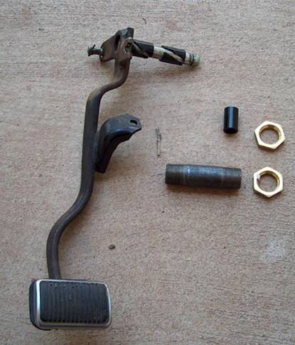
Clutch Pedal installation Since my car originally was an automatic I had to find a clutch pedal assembly to add to my mustang. The assembly was not hard to find but it was expensive. After I got the assembly I compared the clutch pedal assembly with the automatic pedal assembly in my car and I realized that I did not need the entire assembly just the clutch pedal itself. There is a hole in the automatic pedal assembly for a clutch pedal in my mustang but it was missing the bushing that the pedal rides in. A clip at one end of the clutch pedal holds it in place in the assembly.
Clutch pedal assembly with clutch pedal removed. The grey bushing can be seen and is where the clutch pedal rides in the assembly. I measured the distance from the end of one bushing to the other and took the clutch pedal to the hardware store. There I found a piece of pipe of the appropriate length that was threaded at each end and large enough in diameter for the shaft on the clutch pedal fit into. I also found plastic washers to ride on the clutch pedal shaft inside the pipe and a pair of nuts to hold the pipe in the automatic pedal assembly.
Clutch Pedal with plastic bushings installed, Pipe, nuts and an extra bushing.
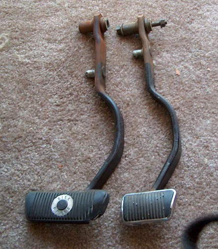
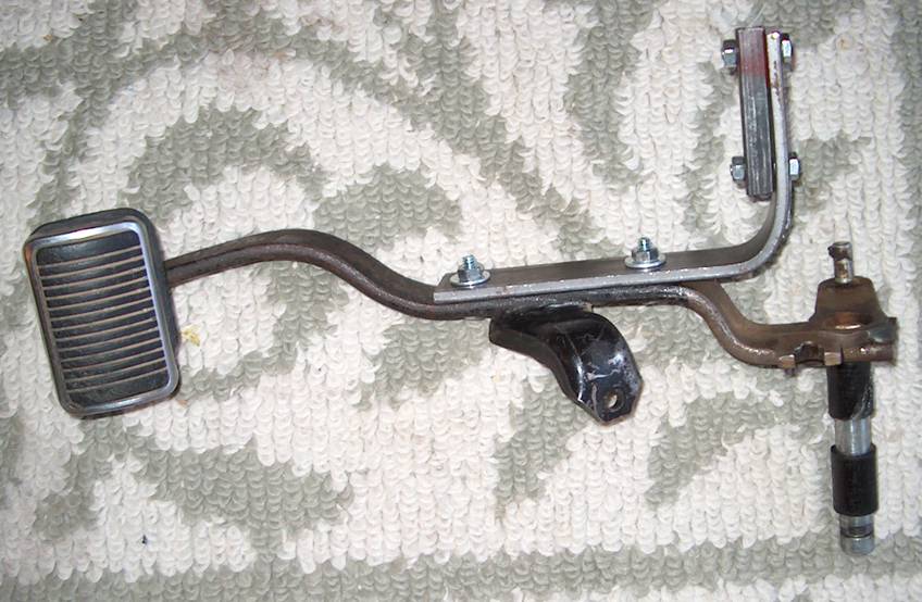
Automatic Brake Pedal next to the Manal Brake Pedal: Notice that the pivot points are in different locations In order to install the clutch pedal I had to remove and shorten the automatic brake pedal. The manual brake pedal that came with the clutch pedal assembly could not be used in the automatic pedal assembly because of where its pivot point is located.
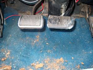
Clutch Pedal installed with shortened Brake Pedal Hydraulic Clutch Actuation System After installing a Tremec 3550 in my mustang I needed to construct some type of clutch actuation system. My initial ideas involved the use of a clutch cable. Unfortunately the mechanical linkage I constructed to connect the clutch pedal to the cable was not strong enough to handle the forces involved in actuating the clutch.
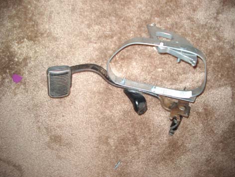
Clutch Pedal with soon to fail clutch cable bracket, a very bad design.
All my attempts to improve the linkage failed so I decided to try a hydraulic set up that I had seen on a post at www.vintage-mustang.com The hydraulic clutch system that I constructed is basically the same as deatman68’s. It uses the same master and slave cylinders as the deathman and the system works flawlessly. Here is a link to that post http://forums.vintage-mustang.com/forums/showflat.php?Cat=&Board=forum&Number=737118&page=&view=&sb=5&o=&fpart=1&vc=1
Parts and Tools The major parts that I needed were in a list I found on another post by deathman68. I ordered the Adjustable pushrod, Master, and slave Cylinders from Mckenzies at http://www.mckenzies.com The rest of the parts I picked up at local hardware and auto parts stores. I omitted item 4 from the parts list and used a ¼ inch thick 36x2 inch strip of steel I had previously purchased to construct a bracket for attaching my slave cylinder to the tremec. I also omitted item 19. Item 15 is a remote reservoir and I found one of those at my local junk yard on a 90 Ford Ranger. I also got the hose that attached the reservoir to the brake master cylinder on the ranger. I had some difficulty finding parts 13 and 14. They are the fittings for the master and slave cylinders. I suggest that you take the cylinders with you and go to a plumbing or farmer’s supply store to find all the fittings you need. Be sure to get a fitting with a 90 degree angle for the slave cylinder. As far as tools go you will need to get cutting bending and flaring tools so that you can route the brake line from the master cylinder to the slave cylinder. These tools are all inexpensive and you will be surprised at how easy they are to use. Deathman’s Parts list:
Item Part No. Price Additional Parts 1. 1- Remote clutch master cylinder reservoir from a 90 ford ranger 2. 1- 1 ft 3/8” fuel hose 3. 1- 1/4” thick 36”x2” Steel strip 4. 1- 36” long 1” square steel tube 5. 6- ¼” x 1” bolts 6. 6- ¼” x 2” bolts 7. 12- ¼” nuts 8. 12- ¼” washers 9. 2- 5/16”-24(fine thread) nuts 10. Dot 3 Brake fluid 11. Thread lock (for the pipe fittings to keep fluid from leaking) 12. Tubing cutter 13. Tube flare tool 14. Tube bending tool
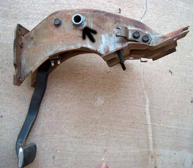
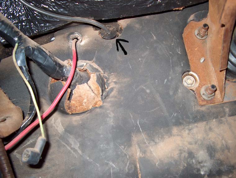
Actuation System Installation Steps Note: I installed all of the pipe fittings into the slave and master cylinders using thread lock to ensure they would not leak before placing them on the car. If you do so keep in mind that you may have to make adjustments to the angled fitting on the slave cylinder after you have routed brake line to it. 1. Find a suitable location on your firewall for the master cylinder. 2. Drill a hole large enough for the master cylinder at that location on my 73 mustang I removed what I think is an original ground wire that ran through the fire wall and reran it through a hole on the right side of the steering column. The hole for the wire and grommet required only slight enlargement to accommodate the master cylinder.
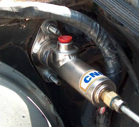
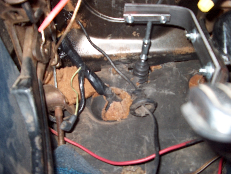
Arrow shows the location of the grommet and wire under the dash 3. Use the master cylinder as a template and drill holes for the ¼” master cylinder mounting bolts in the firewall. 4. Find or make metal plates to go inside the car between the bolt heads and the fire wall for reinforcement. I used a couple of 1/8 steel brackets I had lying around. 5. Mount the Master cylinder to the firewall.
Master Cylnder mounted on the firewall 6. Measure the distance from the clutch pedal arm to the master cylinder pushrod. 7. Remove the clutch pedal, fabricate and attach an arm for actuating the pushrod. I constructed an arm using a 10” piece of the ¼” thick steel strip. I added a 3” piece of ¾” square tubing to the arm. I would later drill a hole in one face of the tube where it meets the pushrod.
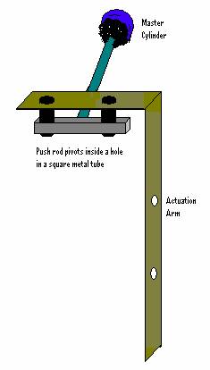
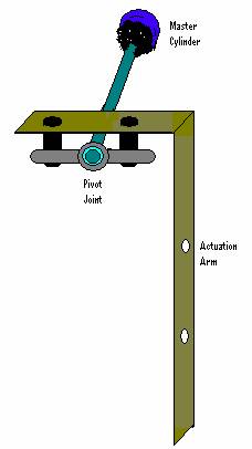
Clutch Pedal with arm installed Note: The diagram below shows what the arm looks like and how it attaches to the pushrod. The hole in the metal tube is only in one side the other is closed so that the rod does not pass threw.
A better design would incorporate some type of pivot ball that attaches to the pushrod and attachment arm. Below is a picture of what the improved design might look like. 8. Reinstall the clutch pedal with the actuation arm installed. 9. Mark the square tube on the arm at the point where it meets the pushrod. You may need to lengthen the pushrod by attaching the 5/16-24 (fine thread) bolt with the coupler nut so you can make this measurement. 10. Remove the clutch pedal and drill a hole in the face of the tube where you marked it would meet the pushrod. 11. Reinstall the clutch pedal with the arm. 12. Place the end of the bolt, which you will have to cut the head off of, into the tube on the actuation arm.
Clutch Pedal Actiation Arm Attached to Master Cylinder Note: As the clutch pedal is pushed in the actuation arm pushes the pushrod into the master cylinder. Since the arm travels in an arch the push rod travels up and down in an angle. In order to insure that the pushrod wouldn’t bind on the walls of the master cylinder as it is pushed in at an angle. I ensured that the pushrod would be initially angled down below the master cylinder’s center line. As the clutch pedal is pushed to the floor the pushrod is forced to angle upward by the arm. At the end of the clutch pedals travel the pushrod is angled upward above the master cylinder’s center line. 13. Fabricate a bracket to attach the slave cylinder to the tremec transmission. Note: I will add measurements and a diagram of my bracket later. It was constructed from the ¼ inch steel strip. 14. Attach the slave cylinder pushrod to the clutch fork. You will have to readjust it later to get the correct clutch engaugement and disengagment points along the clutch pedal’s travel. 15. Determine the route that the brake line will follow from the master to the slave cylinder. 16. Make a diagram of the brake line’s layout with measurements and approx angles. 17. Make your bends in your line and do a test fit in the car. 18. Attach the brake line to the master cylinder then make adjustments to the route, and bends in the line. 19. Determine the final distance and bends to the slave cylinder. Once you are satisfied cut the line the appropriate length and hookup the end to the slave cylinder. 20. Install the brake reservoir in an appropriate place on the fender well or firewall. 21. Attach a hose from the reservoir to the master cylinder. 22. Fill the reservoir with brake fluid. 23. Locate the bleeder on the slave cylinder and get a friend to assist you in bleeding the air out of the line having them press the clutch pedal in while you open the bleeder screw and watch for air bubbles. Closing the screw before they let off the pedal. Be sure to add brake fluid to the clutch reservoir during the bleeding process so that you do not run the master cylinder out of fluid. 24. Test the system and watch for leaks. 25. Adjust the Slave Cylinder pushrod so that the clutch fork engages after the pedal has been pushed in 1¼ inches from its initial position. Then be sure to check that pressing the pedal all the way to the floor does not overextend the clutch fork and bend the fingers that release the clutch inside the bell housing. 26. Tests drive the car and readjust the clutch engagement if necessary.
|